|
The principle of the antenna is used to transmit radio equipment or receive an antenna of electromagnetic components. Radio communications, radio, television, radar, navigation, electronic countermeasures, remote sensing, radio astronomy and other engineering systems all use electromagnetic waves to transmit information and rely on antennas to work. In addition, in terms of energy transmitted by electromagnetic waves, signal energy radiation is not a necessary antenna. Antennas are usually reversible, which is the same as two antennas. The transmitting antenna can be used as a receiving antenna. The transmission or reception is the same as the antenna with the same basic characteristic parameters. This is the antenna reciprocity theorem. \nIn the network vocabulary, antenna refers to certain tests, some are related, and some people can go through the back door shortcut, specifically referring to some special relationships.
Outline
1.Antenna
1.3.2 antenna directivity enhancement
1.3.3 Antenna Gain
1.3.4 Beamwidth
1.3.5 Front to Back Ratio
1.3.6 antenna gain certain approximate formula
1.3.7 Upper sidelobe suppression
1.3.8 Antenna downtilt
1.4.1 dual-polarized antenna
1.4.2 Polarization loss
1.4.3 Polarization Isolation
1.5 Antenna input impedance Zin
1.6 antenna operating frequency range (bandwidth)
1.7 mobile communication base station antennas used, repeater antenna and indoor antenna
1.7.1 Panel Antenna
1.7.1a Base Station Antenna basic technical indicators Example
1.7.1b formation of high-gain panel antenna
1.7.2 High Gain Grid Parabolic Antenna
1.7.3 Yagi directional antenna
1.7.4 Indoor Ceiling Antenna
1.7.5 Indoor Wall Mount Antenna
2. Some basic concepts of wave propagation
2.1 free-space communication distance equation
2.2 VHF and microwave transmission line of sight
2.2.1 The ultimate look into the distance
2.3 wave propagation characteristics in the plane on the ground
2.4 multipath propagation of radio waves
2.5 diffracted wave propagation
3.1 type of transmission line
3.2 The characteristic impedance of the transmission line
3.3 feeder attenuation coefficient
3.4 Matching Concept
3.5 Return Loss
3.6 VSWR
3.7 balancing device
3.7.1 Wavelength Baluns half
3.7.2 quarter wavelength balanced - unbalanced device
4. Feature
Antenna or receiving electromagnetic radiation from space (information) of the device.
Radiation or radio device receives radio waves. It is the radio communications equipment, radar, electronic warfare equipment and radio navigation equipment, an important part. Antennas are usually made of metal wire (rod) or metal surfaces made of the former is called wire antenna, which is known antenna. An antenna for radiating radio waves, said transmitting antenna, it is sent to the transmitter energy is converted into an alternating current electromagnetic energy space. An antenna for receiving radio waves, said receiving antenna, which the electromagnetic energy from the space obtained is converted to an alternating current energy given receiver. Usually a single antenna can be used as the transmitting antenna, receiving antenna can also be used as with the antenna duplexer can send and receive simultaneously share. But some antennas only suitable for receiving antenna.
Describes the electrical properties of the antenna main electrical parameters: pattern, gain coefficient, input impedance, and the band width efficiency. Antenna pattern is a center of the sphere to the antenna either a sphere (radius much larger than the wavelength) on the spatial distribution of the electric field intensity dimensional graphics. Usually contains a maximum radiation direction of the two mutually perpendicular planar direction graph. To concentrate in certain directions of radiating or receiving electromagnetic waves, said antenna directional antenna, the direction shown in Figure 1, the device can increase effective distance, to improve noise immunity. Use certain features of the antenna pattern can be done, such as finding, navigation and directional communications and other tasks. Sometimes in order to further improve the directivity of the antenna, you can put a number of the same type of antenna arrangement according to certain rules together to form an antenna array. Antenna gain factor is: If the antenna is replaced with the desired non-directional antenna, the antenna in the original direction of maximum field strength, the same distance still produce the same field strength conditions, the input power to the non-directional antenna with the input to the actual antenna power ratio. Currently a large microwave antenna gain factor of up to about 10. Antenna geometry and operating wavelength ratio greater directivity stronger, gain coefficient is also higher. Input impedance is presented at the input of the antenna impedance, typically includes two parts resistance and reactance. Affect its value received, the transmitter and the feeder match. Efficiency is: antenna radiation power and its input power ratio. It is the role of an antenna to complete effectiveness of energy conversion. Bandwidth refers to the antenna main performance indicators to meet the requirements when operating frequency range. A passive antenna for transmitting or receiving the electric parameters are the same, which is the antenna reciprocity. Military antennas also have light and flexible, easy to set up, good for hiding invulnerability ability and other special requirements.
Antenna:
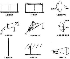
Many shape of the antenna, according to use, the frequency, structure classification. Long, medium band often using the T-shaped, inverted L-shaped umbrella antenna; short wavelength commonly used are bipolar, cage, diamond, log periodic, fishbone antenna; FM lead antenna segments are commonly used ( Yagi antenna), helical antenna, corner reflector antennas; microwave antennas commonly used antennas, such as horn antennas, parabolic reflector antenna, etc.; mobile stations often use the horizontal plane for the non-directional antennas, such as whip antennas. The shape of the antenna shown in Figure 2. Active device is called an antenna with an active antenna, which can increase the gain and to achieve miniaturization, is solely for the receiving antenna. Adaptive antenna is an antenna array and adaptive processor system, it is handled by adaptive output each array element, so that the output signal being the smallest maximum useful signal output, in order to improve communication, radar and other equipment immunity . There microstrip antenna is attached to the dielectric substrate metal radiating element on one side and on the other side of the metal ground floor consisting of, aircraft surfaces with the same shape, with small size, light weight, suitable for fast aircraft .Antenna
Classification:
① Press the nature of the work can be divided into transmitting and receiving antennas.
② can be divided according to purpose communications antenna, radio antenna, TV antenna, radar antennas.
③ Press the operating wavelength can be divided into long-wave antenna, long-wave antenna, AM antenna, shortwave antenna, FM antenna, microwave antennas.
④ Press the structure and working principle can be divided into wire antennas and antenna and so on. Describe a characteristic parameter of the antenna pattern, directivity, gain, input impedance, radiation efficiency, polarization and frequency
Antenna according to dimension points can be divided into two types:
Antenna
One-dimensional and two-dimensional antenna antenna
One-dimensional wire antenna consists of many components, such as wires or used on the phone line, or some clever shape, like a cable on the TV before using an old rabbit ears. Monopole antenna and two-stage two basic one-dimensional antenna.
Dimensional antenna diverse, a sheet (a square metal), array-like (two-dimensional model of a bunch of good tissue slice), as well as trumpet-shaped, dish.
Antenna according to applications can be divided into:
Handheld station antennas, car antennas, base antenna three categories.
Hand-held units for personal use handheld walkie-talkie antenna is an antenna, a common rubber antenna and whip antenna into two categories.
Original design car antenna is mounted on the vehicle communications antenna, the most common is the most widely sucker antenna. Vehicle antenna structure also has a shortened quarter-wave, a sense of the central add type, five-eighths wavelength, dual half wavelength antenna forms.
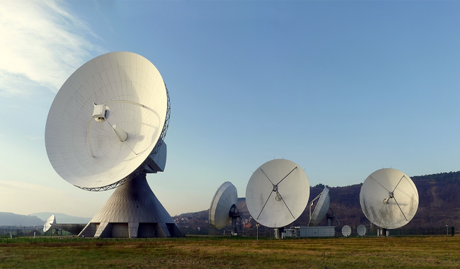
Base station antennas in the whole communication system has a very critical role, especially as a communications hub of communication stations. Commonly used fiberglass base station antenna has high gain antenna, Victoria array antenna (eight ring array antennas), directional antenna.
Radiation:
The capacitor to the antenna to the antenna radiation radiated during the process of capacitor
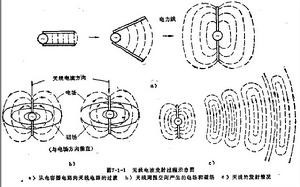
There wire alternating current flows, the electromagnetic radiation can occur, the ability of radiation and the length and shape of the wire. Shown in Figure a, if the two wires in close proximity, the electric field between the wires is bound in two, so radiation is very weak; open the two wires, as shown in b, c, the electric field on the spread in the surrounding space, Radiation. Must be noted that, when the wire length L is much smaller than the wavelength λ, the radiation is weak; wire length L to be compared with the wavelength, the wire will greatly increase the current, and thus can form a strong radiation.
1.2 dipole antenna
Dipole is a classic, antenna far the most widely used, a single half-wave dipole site can be simply used alone or used as feed parabolic antenna, but also can be a plurality of half-wave dipole antenna array formed. Arms of equal length oscillator called dipole. Each arm length is a quarter wavelength, a length of half the wavelength oscillator, said half-wave dipole, shown in Figure 1.2a. In addition, there is a half-wave dipole-shaped, can be regarded as the full-wave dipole converted into a long and narrow rectangular box, and the full-wave dipole stacked two ends of this long and narrow rectangle is called equivalent oscillator, note that the oscillator length is equivalent to half the wavelength, it is called a half-wave equivalent oscillator, shown in Figure
1.3.1 Directional Antenna
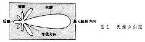
One of the basic functions of the transmitting antenna is to get the energy from the feeder radiated out to the surrounding space, the basic functions of the two is to most of the energy radiated in the desired direction. Vertically placed half-wave dipole has a flat of the "donut"-shaped three-dimensional pattern (Figure 1.3.1a). Although three-dimensional stereoscopic pattern, but difficult to draw Figure 1.3.1b and Figure 1.3.1c shows its two principal plane pattern, graphic depicts the antenna in the direction of a specified plane direction. Figure 1.3.1b can be seen in the axial direction of the transducer zero radiation, the maximum radiation direction in the horizontal plane;
1.3.1c can be seen from the figure, in all directions in the horizontal plane as large as the radiation.
1.3.2 antenna directivity enhancement
Group several dipole array, capable of controlling radiation, resulting in "flat donut", the signal is further concentrated in the horizontal direction.
The figure is four half-wave dipoles arranged in a vertical up and down along the vertical array of four yuan a perspective view and a vertical direction of the drawing direction.
Reflector plate can also be used to control the radiation unilateral direction, plane reflector plate on the side of the array constitutes a sector area coverage antenna. The following figure shows the horizontal direction of the effect of the reflecting surface of the reflecting surface ------ unilateral direction of reflected power and improve the gain.
The use of parabolic reflector, it enables the antenna radiation, such as optics, searchlights, as the energy is concentrated into a small solid angle, resulting in a very high gain. It goes without saying, the composition of parabolic antenna consists of two basic elements: parabolic reflector and parabolic focus placed on the radiation source.
1.3.3 Gain
Gain means: the input power equal conditions, the actual and the ideal antenna radiation element generated at the same point in space of signal power density ratio. It is a quantitative description of the input power of an antenna radiation level concentration. Gain antenna patterns obviously have a close relationship, the more narrow the direction of the main lobe, side lobe is smaller, the higher the gain. Can be understood as the gain ------ physical meaning at a certain distance from a point on the signal of a certain size, if the ideal point source as the non-directional transmitting antenna, to the input power of 100W, and with a gain of G = 13dB = 20 of a directional antenna as a transmitting antenna, input power only 100/20 = 5W. In other words, a gain of the antenna on its direction of maximum radiation of the radiation effect, and non-ideal point source directivity compared amplification of the input power factor.
Half-wave dipole with a gain of G = 2.15dBi.
Four half-wave dipole arranged vertically along the vertical, forming a vertical array of four yuan, and its gain is about G = 8.15dBi (dBi this object is expressed in units of relatively uniform radiation ideal isotropic point source).
If the half-wave dipole for comparison object, the gain of the unit is dBd.
Half-wave dipole with a gain of G = 0dBd (because it is with their own ratio, the ratio is 1, taking the logarithm of zero values.) Vertical four yuan array, its gain is about G = 8.15-2.15 = 6dBd.
1.3.4 Beamwidth
Pattern usually has multiple lobes, where the maximum radiation intensity lobe called the main lobe, the rest of the side lobe or lobes called sidelobes. See Figure 1.3.4a, at both sides of the main lobe direction of maximum radiation, the radiation intensity decreases 3dB (half power density) of the angle between two points is defined as the half-power beamwidth (also known as the beam width or half-width of the main lobe or power angle or-3dB beam width, half-power beamwidth, referred HPBW). The narrower beamwidth, directivity better role farther away, the stronger anti-interference ability. There is also a beam width, i.e. 10dB beam width, suggests that it is the radiation intensity pattern reduces 10dB (down to one tenth of the power density) of the angle between the two points.
1.3.5 Front to Back Ratio
Direction of the figure, the ratio of the maximum front and rear flap called back ratio, denoted by F / B. Greater than before, the antenna backward radiation (or reception) is smaller. Back ratio F / B calculation is very simple ------
F / B = 10Lg {(prior to the power density) / (backward power density)}
Front and rear of the antenna ratio F / B when requested, the typical value (18 ~ 30) dB, exceptional circumstances require up to (35 ~ 40) dB.
1.3.6 antenna gain certain approximate formula
1), the narrower the width of the main lobe of the antenna, the higher the gain. For general antenna, its gain can be estimated by the following formula:
G (dBi) = 10Lg {32000 / (2θ3dB, E × 2θ3dB, H)}
Where, 2θ3dB, E and 2θ3dB, H respectively in two main plane antenna beam width;
32000 is out of the experience of statistical data.
2) For a parabolic antenna, can be approximated by calculating the gain:
G (dBi) = 10Lg {4.5 × (D/λ0) 2}
Wherein, D is the diameter of the paraboloid;
λ0 for the center wavelength;
4.5 out of empirical statistical data.
3) for vertical omnidirectional antenna, with approximate formula
G (dBi) = 10Lg {2L/λ0}
Where, L is the antenna length;
λ0 for the center wavelength;
Antenna
1.3.7 Upper sidelobe suppression
For the base station antenna, often requires its vertical (i.e. the elevation plane) direction of the figure, the top of the first side lobe lobe as weaker. This is called the upper side lobe suppression. Base station is serving the mobile phone users on the ground, pointing to the sky radiation is meaningless.
1.3.8 Antenna downtilt
To make the main lobe pointing to the ground, placing the antenna requires moderate declination.
1.4.1 dual-polarized antenna
The following figure shows the other two unipolar situation: +45 ° polarization and -45 ° polarization, they are only used on special occasions. Thus, a total of four unipolar, see below. The vertical and horizontal polarization antenna together two polarizations, or the +45 ° polarization and -45 ° polarization of the two polarization antenna combined together, constitute a new antenna --- dual-polarized antennas.
The following diagram shows two unipolar antenna is mounted together to form a pair of dual-polarized antenna, note that there are two dual-polarized antenna connector.
Dual-polarized antenna (or receiving) two spatially mutually orthogonal polarization (vertical) wave.
1.4.2 Polarization loss
Use a vertically polarized wave antenna with vertical polarization characteristics to receive, use the horizontal polarized wave antenna with horizontal polarization characteristic to receive. Use a right-hand circularly polarized wave antenna right circular polarization characteristics to receive, and to use a left-handed circularly polarized wave characteristic LHCP
antenna reception.
When the incoming wave polarization direction of the polarization direction of the receiving antenna match, the received signal will be small, that is, the occurrence of polarization losses. For example: When a +45 ° polarized antenna receives the vertical polarization or horizontal polarization, or, when the vertically polarized antenna polarization or -45 ° +45 ° polarized wave, etc. case, To generate polarization losses. A circular-polarization antenna to receive a linearly polarized plane wave, or linear polarization antenna with either circularly polarized waves, so the situation, it is also inevitable loss of polarization can receive incoming waves ------ half the energy.
When the polarization direction of the receiving antenna to the direction of polarization of the wave is completely orthogonal, for example, receiving antenna horizontally polarized to vertically polarized waves, or right-handed circularly polarized receiving antenna LHCP The incoming wave, the antenna can not be completely received wave energy, in which case the maximum loss of polarization, said polarization completely isolated.
1.4.3 Polarization Isolation
Ideal polarization is not completely isolated. Fed to the antenna to one polarization signal how much there will always be a little bit in another polarized antenna appears. For example, the dual polarized antenna shown, the set input vertical polarization antenna power is 10W, the results in a horizontal polarization antenna measured at the output of the output power of 10mW.
1.5 Antenna input impedance Zin
Definition: antenna input signal voltage and signal current ratio, known as the antenna input impedance. Rin has a resistive component of the input impedance and reactance component Xin, namely Zin = Rin + jXin. Reactance component of the antenna will reduce the presence of signal power from the feeder to the extraction, so as to make the reactance component is zero, that is, as far as possible to the antenna input impedance is purely resistive. In fact, even the design, debugging very good antenna, the input impedance also includes a small total reactance values.
Input impedance of the antenna structure, the size and the operating wavelength, half-wave dipole antenna is the most important basic, the input impedance Zin = 73.1 + j42.5 (Europe). When the length is shortened (3-5)%, it can be eliminated where the reactance component of the antenna input impedance is purely resistive, then the input impedance of Zin = 73.1 (Europe), (nominally 75 ohms). Note that strictly speaking, purely resistive input impedance of the antenna is just right in terms of frequency points.
Incidentally, the half-wave oscillator equivalent input impedance of a half-wave dipole four times, i.e. Zin = 280 (Europe), (nominal 300 ohms).
Interestingly, for any antenna, the antenna impedance by people always debugging, the required operating frequency range, the imaginary part of the input impedance real part of small and very close to 50 Ohms, so that the antenna input impedance Zin = Rin = 50 Ohms ------ antenna to the feeder is in a good impedance matching necessary.
1.6 antenna operating frequency range (bandwidth)
Both the transmitter antenna or reception antenna, which are always in a certain frequency range (bandwidth) of the work, the bandwidth of the antenna, there are two different definitions ------
One is means: SWR ≤ 1.5 VSWR conditions, the antenna operating frequency band width;
One is the means: down 3 db antenna gain within the band width.
In mobile communication systems, it is usually defined by the former, specifically, the bandwidth of the antenna SWR SWR is not more than 1.5, the antenna operating frequency range.
Generally, the operating band width of each frequency point, there is a difference in antenna performance, but the performance degradation caused by this difference is acceptable.
1.7 mobile communication base station antennas used, repeater antenna and indoor antenna
1.7.1 Panel Antenna
Both GSM and CDMA, Panel Antenna is one of the most commonly used class of extremely important base station antenna. This antenna's advantages are: high gain, pie slice pattern is good, after the valve is small, easy to control vertical pattern depression, reliable sealing performance and long service life.
Panel Antenna is also often used as a repeater antenna users, according to the scope of the role of fan zone size should select the appropriate antenna models.
1.7.1a Base Station Antenna basic technical indicators Example
Frequency range 824-960MHz
70MHz bandwidth
Gain 14 ~ 17dBi
Polarization Vertical
Nominal impedance 50Ohm
VSWR ≤ 1.4
Front to Back Ratio> 25dB
Tilt (adjustable) 3 ~ 8 °
Half-power beamwidth horizontal 60 ° ~ 120 ° vertical 16 ° ~ 8 °
Vertical plane sidelobe suppression <-12dB
Intermodulation ≤ 110dBm
1.7.1b formation of high-gain panel antenna
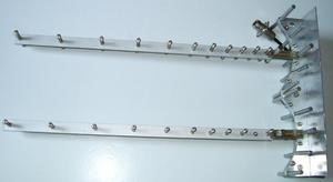
A. with multiple half-wave dipole arranged in a linear array placed vertically
B. In the linear array on one side plus a reflector (reflector plate to bring two half-wave dipole vertical array as an example)
Gain is G = 11 ~ 14dBi
C. In order to improve the gain panel antenna can be further used eight half-wave dipole row array
As noted, the four half-wave dipoles arranged in a linear array of vertically placed gain is about 8dBi; side plus a reflector plate quaternary linear array, namely conventional panel antenna, the gain is about 14 ~ 17dBi .
Plus side there is a reflector eight yuan linear array, ie elongated plate-like antenna, the gain is about 16 ~ 19dBi. It goes without saying, elongated plate-like antenna length for conventional plate antenna doubled to around 2.4m.
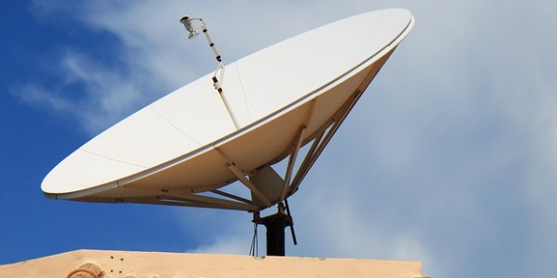
1.7.2 High Gain Grid Parabolic Antenna
From cost-effective way, it is often used as a Grid Parabolic Antenna repeater donor antenna. As a good focus parabolic effect, so paraboloid set of radio capacity, 1.5m diameter parabolic antenna of the grid-like, in the band 900 megabytes, the gain can be reached G = 20dBi. It is particularly suitable for point to point communication, such as it is often used as a repeater donor antenna.
Parabolic grid-like structure used, first, in order to reduce the weight of the antenna, the second is to reduce wind resistance.
Parabolic antenna can usually be given before and after the ratio of not less than 30dB, which is the repeater system against self-excited and made the receiving antenna must meet the technical specifications.
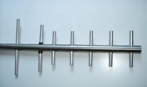
1.7.3 Yagi directional antenna
Yagi directional antenna with high gain, compact structure, easy to set up, cheap, etc.. Therefore, it is particularly suitable for point to point communication, for example, indoor distribution system which is outside the preferred type of antenna receiving antenna.
Yagi antenna, the more the number of cells, the higher the gain, usually 6-12 unit directional Yagi antenna, the gain of up to 10-15dBi.
1.7.4 Indoor Ceiling Antenna
Indoor ceiling antenna must have a compact structure, beautiful appearance, easy installation.
Seen on the market today indoor ceiling antenna, shape many colors, but its share of the inner core made almost all the same. The internal structure of this ceiling antenna, although the size is small, but since it is based on the theory broadband antenna, the use of computer-aided design, and the use of a network analyzer for debugging, it can satisfy the work in a very wide frequency band VSWR requirements, in accordance with national standards, working in a wide band antenna index of the standing wave ratio VSWR ≤ 2. Of course, to achieve better VSWR ≤ 1.5. Incidentally, indoor ceiling antenna is a low-gain antenna, usually G = 2dBi.
1.7.5 Indoor Wall Mount Antenna
Indoor wall antenna must also have a compact structure, beautiful appearance, easy installation.
Seen on the market today indoor wall antenna, shape color a lot, but it made the inner core of the share is almost the same. The inner wall structure of the antenna, are air dielectric type microstrip antenna. As a result of broadening the bandwidth auxiliary antenna structure, the use of computer-aided design, and the use of a network analyzer for debugging, they are able to better meet the work requirements of broadband. Incidentally, indoor wall antenna has a certain gain of about G = 7dBi.
2 Some basic concepts of wave propagation
Currently GSM and CDMA mobile communication bands used are:
GSM :890-960MHz ,1710-1880MHz
CDMA :806-896MHz
806-960MHz frequency range of an FM range; 1710 ~ 1880MHz frequency range is the microwave range.
Waves of different frequencies, or different wavelengths, its spread characteristics are not identical, or even very different.
2.1 free-space communication distance equation
Let transmit power PT, transmitting antenna gain GT, operating frequency f. Received power PR, receiving antenna gain GR, sending and receiving antenna distance is R, then the radio environment in the absence of interference, the radio wave propagation loss en route L0 has the following expression:
L0 (dB) = 10Lg (PT / PR)
= 32.45 +20 Lgf (MHz) +20 LgR (km)-GT (dB)-GR (dB)
[Example] Let: PT = 10W = 40dBmw; GR = GT = 7 (dBi); f = 1910MHz
Q: R = 500m time, PR =?
Answer: (1) L0 (dB) is calculated
L0 (dB) = 32.45 +20 Lg1910 (MHz) +20 Lg0.5 (km)-GR (dB)-GT (dB)
= 32.45 +65.62-6-7-7 = 78.07 (dB)
(2) PR Calculation
PR = PT / (107.807) = 10 (W) / (107.807) = 1 (μW) / (100.807)
= 1 (μW) / 6.412 = 0.156 (μW) = 156 (mμW)
Incidentally, 1.9GHz radio in the penetration layer of brick, about loss (10 ~ 15) dB
2.2 VHF and microwave transmission line of sight
2.2.1 The ultimate look into the distance
FM particular microwave, high frequency, the wavelength is short, its ground wave decay quickly, so do not rely on ground wave propagation over long distances. FM particular microwave, mainly by the spatial wave propagation. Briefly, the spatial wave range in the spatial direction of a wave propagating along a straight line. Obviously, due to the Earth's curvature of space wave propagation exists a limit stare into the distance Rmax. Look at the farthest distance from the area, traditionally known as lighting zone; extreme distance Rmax look outside the area then known as the shaded area. Without saying that language, the use of ultrashort wave, microwave communication, transmitting antenna receiving point should fall within the limits of optical range Rmax. By the radius of curvature of the earth, from the look limit Rmax and transmitting antenna and receiving antenna height HT, the relationship between HR: Rmax = 3.57 {√ HT (m) + √ HR (m)} (km)
Taking into account the role of atmospheric refraction on the radio, the limit should be revised to look into the distance
Rmax = 4.12 {√ HT (m) + √ HR (m)} (km)
Antenna
Since the frequency of the electromagnetic wave is much lower than the frequency of light waves, wave propagation effective stare into the distance from Re Rmax look around the limit of 70%, ie, Re = 0.7Rmax.
For example, HT and HR respectively 49m and 1.7m, the effective optical range of Re = 24km.
2.3 wave propagation characteristics in the plane on the ground
Directly irradiated by the transmitting antenna radio reception point is called the direct wave; transmitting antenna of the radio waves emitted pointing to the ground, by the ground reflected wave reaches the receiving point is called the reflected wave. Clearly, the reception signal point should be the direct wave and the reflected wave synthesis. Synthesis of wave not like 1 +1 = 2 as simple algebraic sum of results with synthetic direct wave and the reflected wave path difference between waves differ. Wave path difference is an odd multiple of a half wavelength, the direct wave and the reflected wave signal, to synthesize the maximum; wave path difference is a multiple of the wavelength, the direct wave and the reflected wave signal subtraction, synthesis is minimized. Seen, the presence of ground reflection, so that the spatial distribution of the signal intensity becomes quite complex.
Actual measurement point: Ri of a certain distance, the signal strength with increasing distance or antenna height will be undulation; Ri at a certain distance, the distance increases with the degree of reduction or antenna, the signal strength will be. Decreases monotonically. Theoretical calculation gives the Ri and antenna height HT, HR relationship:
Ri = (4HTHR) / l, l is the wavelength.
It goes without saying, Ri must be less than the limit stare into the distance Rmax.
2.4 multipath propagation of radio waves
In FM, the microwave band, radio in the dissemination process will encounter obstacles (eg buildings, tall buildings or hills, etc.) have a reflection on the radio. Therefore, there are many to reach the receiving antenna reflected wave (broadly speaking, the ground reflected wave should also be included), this phenomenon is called multipath propagation.
Due to multipath transmission, making the spatial distribution of the signal field strength becomes quite complex, volatile, enhanced signal strength in some places, some local signal strength weakened; also because of the impact of multipath transmission, but also to make waves the polarization direction changes. In addition, different obstacles on the radio wave reflection have different capacities. For example: reinforced concrete buildings on FM, microwave reflectivity stronger than a brick wall. We should try to overcome the negative effects of multipath propagation effects, which is in communication requiring high quality communication networks, people often use spatial diversity or polarization diversity techniques reason.
2.5 diffracted wave propagation
Encountered in the transmission of large obstacles, the waves will propagate around obstacles ahead, a phenomenon called diffraction waves. FM, microwave high frequency wave length, diffraction weak, the signal strength in the back of a tall building is small, the formation of so-called "shadow." The degree of signal quality is affected, not only related to the height and the building, and the receiving antenna on the distance between the building but also, and frequency. For example there is a building with a height of 10 meters, the building behind the distance of 200 meters, the received signal quality is almost unaffected, but in the 100 meters, the received signal field strength than that without buildings decreased significantly. Note that, as above said, the weakening extent also with the signal frequency, for 216 to 223 MHz RF signal, the received signal field strength than that without buildings low 16dB, for 670 MHz RF signal, the received signal field No buildings low intensity ratio 20dB. If the building height to 50 meters, then at a distance of less than 1000 meters of buildings, the field strength of the received signal will be affected and weakened. That is, the higher the frequency, the higher the building, the more receiving antenna near the building, the signal strength and the greater the degree of communication quality affected; Conversely, the lower the frequency, the more low buildings, building farther receiving antenna , the impact is smaller.
Therefore, selecting a base station site and set up an antenna, be sure to take into account diffraction propagation possible adverse effects, noted the diffraction propagation from a variety of factors influence.
Three transmission lines a few basic concepts
Connect the antenna and transmitter output (or receiver input) cable called transmission line or feeder. The main task of the transmission line is to efficiently transmit signal energy, therefore, it should be able to send out the transmitter signal power with minimal loss to the input of the transmitting antenna, or the antenna received signal transmitted with minimal loss to the receiver inputs, and it should not itself stray interference signals picked up or so, requires transmission lines must be shielded.
Incidentally, when the physical length of the transmission line is equal to or greater than the wavelength of the transmitted signal, the transmission line is also called long.
3.1 type of transmission line
FM transmission line segments are generally two types: parallel wire transmission lines and coaxial transmission line; microwave band transmission lines are coaxial cable transmission line, waveguide and microstrip. Parallel wire transmission line formed by two parallel wires which is symmetrical or balanced transmission line, this feeder loss, can not be used for the UHF band. Coaxial transmission line two wires were shielded core wire and copper mesh, copper mesh ground because, two conductors and earth asymmetry, so called asymmetrical or unbalanced transmission lines. Coax operating frequency range, low loss, coupled with a certain electrostatic shielding effect, but the interference of the magnetic field is powerless. Avoid use with strong currents parallel to the line, the line can not be close to the low-frequency signal.
3.2 The characteristic impedance of the transmission line
Around an infinitely long transmission line voltage and current ratio is defined as the transmission line characteristic impedance, Z0 represents a. The characteristic impedance of the coaxial cable is calculated as
Z. = [60 / √ εr] × Log (D / d) [Euro].
Wherein, D is the inner diameter of the coaxial cable outer conductor copper network; d of the cable wire diameter;
εr is the relative dielectric between conductors permittivity.
Typically Z0 = 50 Ohms, there Z0 = 75 ohm.
It is obvious from the above equation, the characteristic impedance of the feeder conductors only with the diameter D and d, and the dielectric constant εr between conductors, but not with the feeder length, frequency and feeder terminal regardless of the connected load impedance.
3.3 feeder attenuation coefficient
Feeder in the signal transmission, in addition to the resistive losses in the conductor, the dielectric loss of the insulating material there. Both loss with line length increases and the operating frequency increases. Therefore, we should try to shorten the rational distribution feeder length.
Unit length of the size of the loss generated by the attenuation coefficient β expressed in units of dB / m (dB / m), cable technology most of the instructions on the unit with dB/100m (db / one hundred meters).
Let the power input to the feeder P1, from the length of L (m) the power output of the feeder is P2, the transmission loss TL can be expressed as:
TL = 10 × Lg (P1/P2) (dB)
Attenuation coefficient
β = TL / L (dB / m)
For example, NOKIA7 / 8 英寸 low cable, 900MHz attenuation coefficient β = 4.1dB/100m, can be written as β = 3dB/73m, that is, the signal power at 900MHz, each through this cable length 73m , the power to less than half.
The ordinary non-low cable, for example, SYV-9-50-1, 900MHz attenuation coefficient β = 20.1dB/100m, can be written as β = 3dB/15m, that is, a frequency of 900MHz signal power, After each 15m long this cable, the power will be halved!
3.4 Matching Concept
What is the match? Simply put, the feeder terminal connected to the load impedance ZL is equal to the characteristic impedance Z0 feeder, the feeder terminal is called a matching connection. Match, there is only transmitted to the feeder terminal load incident, and no load is generated by the terminal of the reflected wave, therefore, the antenna load as a terminal, to ensure that the antenna matching to obtain all the signal power. As shown below, the same day when the line impedance of 50 Ohms, with a 50 ohm cables are matched, and the day when the line impedance of 80 Ohms, with a 50 ohm cables are mismatched.
If thicker diameter antenna element, the antenna input impedance versus frequency is small, easy to maintain match and feeder, then the antenna on a wide range of operating frequencies. On the contrary, it is narrower.
In practice, the input impedance of the antenna will be affected by the surrounding objects. In order to make a good match with the antenna feeder, will also be required in the erection of the antenna by measuring, appropriate adjustments to the local structure of the antenna, or add matching device.
3.5 Return Loss
As noted, when the feeder and antenna matching, the feeder is not reflected waves, only the incident, which is transmitted to the feeder traveling wave antenna. At this time, the feeder voltage amplitude throughout the current amplitude are equal, the impedance of the feeder at any point is equal to its characteristic impedance.
And the antenna and feeder do not match, the antenna impedance is not equal to the characteristic impedance of the feeder, the feeder load can only absorb the high-frequency energy on the part of the transmission, and can not absorb all of that part of the energy is not absorbed will be reflected back to form reflected wave.
For example, in the figure, since the impedance of the antenna and feeder type, a 75-ohm, a 50 ohm impedance mismatch, the result is
3.6 VSWR
In case of mismatch, the feeder simultaneously incident and reflected waves. Phase of the incident and reflected waves the same place, the voltage amplitude of the maximum voltage amplitude sum Vmax, forming antinodes; incident and reflected waves in opposite phase relative to the local voltage amplitude is reduced to the minimum voltage amplitude Vmin, the formation of the node. Other amplitude value of each point is between antinodes and the node between. This synthetic wave called a row standing.
Reflected wave voltage and the ratio is called the incident voltage amplitude reflection coefficient, denoted by R
Reflected wave amplitude (ZL-Z0)
R = ─ ─ ─ ─ ─ = ─ ─ ─ ─ ─ ─ ─
Incident wave amplitude (ZL + Z0)
Antinode amplitude voltage node voltage standing-wave ratio as the ratio, also called the voltage standing wave ratio, denoted VSWR
Voltage amplitude antinode Vmax (1 + R)
VSWR = ─ ─ ─ ─ ─ ─ ─ ─ ─ ─ ─ ─ ─ ─ = ─ ─ ─ ─
The degree of convergence node voltage Vmin (1-R)
Terminating load impedance ZL and the characteristic impedance Z0 closer, the reflection coefficient R is smaller, VSWR is closer to 1, the better match.
3.7 balancing device
The source or the load or transmission line, based on their relationship to the ground, can be divided into two types of balanced and unbalanced.
If the signal source and the ground voltage between both ends of equal opposite polarity, is called the balanced signal source, otherwise known as the unbalanced signal source; if the load voltage between both ends of the ground equal and opposite polarity, is called load balancing, otherwise known as unbalanced load; if the transmission line impedance between the two conductors and ground the same, it is called balanced transmission line, otherwise unbalanced transmission line.
In the unbalanced load imbalance between the signal source and coaxial cable should be used in the balance between the signal source and the load balancing should be used to connect parallel wire transmission lines, so as to efficiently transmit signal power, otherwise they do not balance or the balance will be destroyed and can not work properly. If we want to balance the load unbalanced transmission line and connected, the usual approach is to install between grain "balanced - unbalanced" conversion device, commonly referred balun.
3.7.1 Wavelength Baluns half
Also known as the "U" shaped tube balun, which is used to balance the load unbalanced feeder coaxial cable with a half-wave dipole connection between. "U" shaped tube there is a 1:4 balun impedance transformation effect. Mobile communication system using coaxial cable characteristic impedance is typically 50 in Europe, so in YAGI antenna, using a half-wave dipole equivalent to the impedance adjustment to 200 Euro or so, to achieve the ultimate and main feeder impedance 50 ohm coaxial cable .
3.7.2 quarter wavelength balanced - unbalanced device
Using the quarter-wavelength transmission line termination circuit open nature of the high-frequency antenna to achieve balanced input port and the output port of the coaxial feeder balance between unbalanced - unbalanced conversion.
4.Feature
A) Polarization: antenna emits electromagnetic waves can be used for vertical polarization or horizontal polarization. When the interference antenna (or transmitting antenna) and sensitive equipment antenna (or receiving antenna) the same polarization characteristics, radiation-sensitive devices in the induced voltage generated at the input strongest.
2) Directivity: space in all directions toward the source of interference radiated electromagnetic interference or sensitive equipment receives from all directions electromagnetic interference capability is different. Describe radiation or reception parameters of said directional characteristics.
3) polar plot: Antenna The most important feature is its radiation pattern or polar diagram. Antenna polar diagram is radiated from a different angle directions of the power or field strength diagram formed
4) Antenna gain: antenna directivity antenna power gain G expression. G in either direction the loss of the antenna, the antenna radiation power is slightly less than the input power
5) Reciprocity: the receiving antenna polar diagram is similar to the transmitting antenna polar diagram. Therefore, the transmit and receive antennas no fundamental difference, but sometimes not reciprocal.
6) Compliance: adherence antenna frequencies, the band in its design can effectively work in the outside of this frequency is inefficient. Different shapes and structures of the frequency of electromagnetic wave received by the antenna are different.
Antenna is widely used in radio business. Electromagnetic compatibility, the antenna is mainly used as measurement of electromagnetic radiation sensors, electromagnetic field is converted to an alternating voltage. Then with the electromagnetic field strength values obtained antenna factor. Therefore, EMC measurement in antennas, antenna factor required higher precision, good stability parameters, but wider band antenna.
5 The antenna factor
Is the measured field strength values antenna measured with the receiver antenna output port voltage ratio. Electromagnetic compatibility and its expression is: AF = E / V
Logarithmic representation: dBAF = dBE-dBV
AF (dB / m) = E (dBμv / m)-V (dBμv)
E (dBμv / m) = V (dBμv) AF (dB / m)
Where: E - antenna field strength, in units of dBμv / m
V - the voltage at the antenna port, the unit is dBμv
AF-antenna factor, in units of dB / m
Antenna factor AF should be given when the antenna factory and regularly calibrated. Aerial antenna factor given in the manual, are generally in the far-field, non-reflective, and 50 ohm load measured under.
|