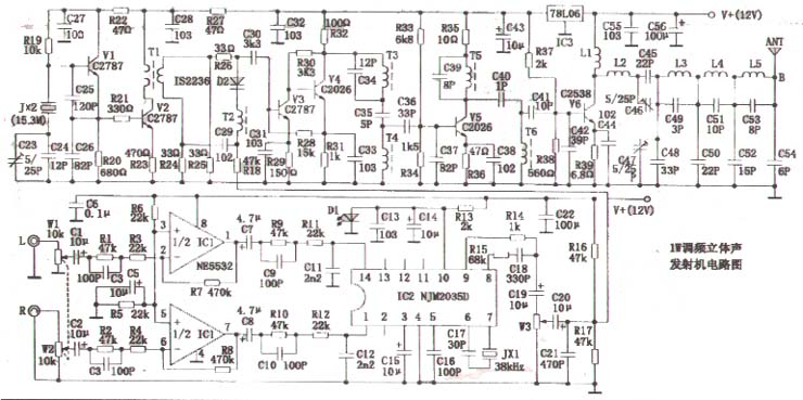
This article describes 1W FM stereo transmitter unit from the audio modulation circuits and radio frequency modulated wave amplification circuit unit composed of two parts. Audio modulation unit circuits of the two IC, debugging becomes extremely simple. Modulated wave RF amplifier circuit of the main vibration level off with crystal frequency stabilization, the phase modulation circuit after another in the oscillator circuit, so the machine high frequency stability. Harmonic-class LC resonant circuit with selective frequency pass band and rectangular coefficient is small, with a good pair of special frequency selective frequency tuning circuit, the resonant frequency of the spurious unwanted harmonic outside a huge extent. The final amplifier output connected multi-section band-pass, low pass filter so that the wireless radio waves transmitted out one more pure, even if the TV is also close to work would not be disturbed. Is a generic for lovers of high-performance radio communications transmitter. Circuit as shown. Audio modulation circuits use high quality dual pre-amplifier IC1 price qian Jiang Sheng op amp NE5532. Li Hugh acoustic signal integrated circuit IC2 use NNJM2035D. To poker machines dynamic microphones or CD were from high-fidelity audio signals L, R-ended input, by W1, W2 coaxial potentiometer control input signal after the voltage range for high fidelity amplification into IC1. IC2 has ○ 1 foot, ○ 14 feet for the stand off-sound audio signal input through the internal functions of this IC circuit after a series of processing the output from the synthesis ○ 9 feet stand off acoustic signal. This signal ○ 8-pin output 19KHZ pilot signal superimposed by the W3 choose the right amount of signal sent to the RF circuit components of the phase after the transfer level. The main transmitter from the crystal vibration level V1, the composition components such as crystal JX2. Oscillation frequency FO = 15.3MHAZ. V2 is a buffer amplifier stage, the output signals coupled to phase modulation by the T1 level, to be its audio signal to modulate. Varactor diode D2, inductor T2, resistors R24, R25, R26 phase modulator composed of bridge. R24, R25, R26 phase modulator, respectively bridge the three bridge arms, the fourth leg from the T2, D2 form. Audio modulation signal by C20, R18 added to the fourth leg. PM FM signal generated by the C30 sent to V3, V4 buffer amplified by T3, C34, C35, T4, C36, C37 consisting of selected double-tuned frequency selection circuit 3 times FO sine wave signal that FO × 3 = 15.3 × 3 = 45.9MHZ. V5 This secondary harmonic frequency signal amplified by the T5, C39, C40, T6, C41, C42 composed of double-tuned frequency selection circuit selected (45.9 × 2 = 91.8MHZ) second harmonic signal is sent to the V6 to power amplifier. V6 output RF amplifier signal by L2 ~ L5, C45 ~ C54 consisting of band-pass, low pass (and impedance matching) filter filter out unwanted harmonics can be carried to the antenna radiation radio waves to the surrounding space. Production, the audio circuit and the RF modulation unit cell circuit to be produced in two circuit boards, respectively. RF unit circuit shielding measures should be taken as a whole. W1, W2 for the coaxial volume potentiometer, IC1 use of inexpensive and quality Liangsheng op amp NE5532. IC2 use NJM2035D. JX1 use 38kHZ crystal. Use an ordinary light-emitting diode D1. W3 fine-tuning for the 10K resistor. R1 ~ R18 choose 1/16W colored ring of metal film resistors. C1 ~ C21 use high-quality capacitors. JX2 use 15.3MHZ crystal. C23, C46, C47 are 5/25PF high-frequency fine-tuning capacitor. V1, V2, V3 use 22SC2787, V4, V5 choose 22SC2026. V6 used 22SC2538, the control parameters: PCM = 3W, ICM = 0.4A, FT = 175MHZ. Varactor diode D2 use IIS2236. C23 ~ C56 than C42, C56 for the high-quality electrolytic capacitors, the other tiles are high-frequency capacitor. R19 ~ R38 ordinary use 1/8W carbon film resistors, R39 use 1W carbon film resistors. T1 ~ T6 are in the 7 × 7 high frequency in the week made the wound, T1 high-frequency primary Φ0.21mm enameled wire with 1 to 3 slot in the winding 6 turns, the secondary tank in the first 3 Turn around 3; T2 high frequency with Φ0.21mm enameled in paragraphs 1, 2 slot all around 9 turns; T3, T4 enameled with Φ0.38mm high-frequency slots in the first 1 to 3 turns each around 2; T5 , T6 high-frequency enameled with Φ0.38mm 2 to 3 slot in around two turns each. L1 ~ L5 is the diameter of 3.5mm enameled wire core high-frequency inductors, high frequency are used Φ0.51mm made of enameled wire wound, L1 around 5 turns, L2 4 turns around, L3 around 5 turns, L4 3 turns around, L5 Turn around 5. IC3 use LM78L067. Antenna with double cross-shaped omni-directional antenna, to stand at more than 10 meters above the ground high quality coaxial cable with 75-5 lead to the RF output of this machine can. Debug circuit should first access 75Ω RF output frequency false load resistance to prevent damage to the RF power when the load control V6. High voltage meter measured at V2's collector voltage of 2V that high-frequency vibration from the normal V1, the test with a frequency meter measuring stick point V2 of the collector, the use of non-sense of a small screwdriver to adjust the fine tuning capacitor C23 value for the frequency counter display "15.300MHZ" that completed a LO buffer amplifier stage of debugging. High Frequency Voltage measured in V4 of the collector voltage of 5V high frequency that V3, V4 buffer amplifier stage is working properly. Adjust the T3, T4's core high-frequency voltage to the base table on the V5 to the high rate of total measured value is displayed as "45.900MHZ" that completed a three-frequency circuit debugging. Adjust the T5, T6 of the core so that the base V6, the frequency counter display value as "91.800MHZ" which completed the second harmonic circuit debugging. Mapping of High Frequency Voltage point marked A high frequency voltage, adjust the fine tuning capacitor C46, C47 to A point of high-frequency voltage ≥ 12V. Mapping of High Frequency Voltage point marked B in the high-frequency voltage, with no sense of a flat screwdriver Toggle L3, L4, L5 to turn away, so that B points, the high frequency voltage ≥ 10V, frequency meter probe in the distance false load 10 ~ 20cm away sensing, frequency meter display value as "91.800MHZ" stability constant that is completed L3 ~ L5, C49 ~ C54 consisting of band-pass, low pass filter preliminary test. Remove the false load access antenna Field emission experiment, I found that the output power ratio of access to fake the output power of a small load. Mainly in the B point for the diagram of low voltage high frequency of many shows at this time of the antenna impedance less than 75Ω. Flat with no sense of a small screwdriver were Toggle L3, L4, L5's turn away from, so that B points to the high-frequency test voltage ≥ 10V is completed V6, L2 ~ L5 level components, such as wiping the composition of formal power amplifier output circuit debugging. Audio modulation circuit debug module and FM stereo radio Yang be combined with the conduct. L, R into the CD machine end of high-fidelity audio output signal, and then hand-held FM stereo radio to listen to a certain distance. Input to the L, R end of the signal amplitude is too strong, the receiver hears the noise signal is turbid, then counter-clockwise adjustment W1, W2 are knob until the receiver to hear the right sound signals clearly identified date. If listening to the voice signal and restore the limiting distortion, the FM modulator bias potentiometer W3, until the receiver came up the sound signal fidelity reproduction. After more debugging, you can hand to test the FM stereo radio emission from the. Receiver sensitivity of 500μV with ordinary FM stereo radio receiver, the open land around 1.5km distance, non-open to a distance of about 500m, FM stereo indicator light properly. The receiver sensitivity 0.5μV senior FM stereo radio receiver, the open field from more than 5km, and the stereo indicator light is still normal.
Our other product: